Page 15 - 810 Trianing Book Extract
P. 15
Where to mount the sensor?
Hints and tips
It is really quite simple: mount the sensor on solid metal anywhere on—or
near—the bearings
Where to mount the sensor?
For vibration testing, we can sim-
plify things to a simple shaft with
What doesn’t really matter?
Why?
2 bearings. Look at your machine—
Exact repeatability (same place)
Noise and variables are designed into the
identify the shaft, bearings, baseline
coupling, and driven element. Then
Sensor location (top, side, end)
The 3 sensors are all the same; same
mount the triaxial sensor on the diagnostic results either way
bearing housing or as close to the
bearing as possible.
Measure from every bearing
Bearings that are close will have the same
information
What is very critical?
Why?
Enter correct motor speed
Speed is the most important factor in vibration
testing
Ensure sensor mounting is secure
Bad data leads to bad results. You can’t ix
bad data
Normal operating conditions
Abnormal operating conditions (changing load)
looks like a fault
Where to mount sensors: see arrows indicating mounting locations on bearings
The following pages have several examples of the many locations that you can select on a machine bearing to
measure good data. Just pick one. One location or direction is not any better than another.
The criteria for location selection should be based on the following: no obstructions, lat metal surface, easy
access, solid and heavy metal that is in direct contact with the bearings.
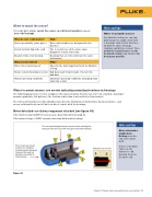
Motor detached—no driven component attached (see igure 44)
If the motor is small (40HP or less), measure data from motor bearing #2.
If the motor is large (>40HP), measure data from both motor bearings.
Hints and tips
Do not mount magnet/sensor across motor cooling ins
because they are not solid enough to transmit vibration.
Motor detached =
stand-alone.
Nothing is on the
end of the motor
shaft.
Fan covers are a bad If there is no good
location for vibration Machine icon in 810
choice on the
measurements because
they are thin and not motor free end
directly connected to bearing, then use
the bearings
the drive end.
Figure 44
Chapter 4: Step-by-step: setup and measure your machines 73