Page 5 - Pressure Calibration Brochure
P. 5
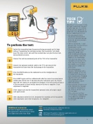
Pressure Module


754 DOCUMENTING PROCESS CALIBRATOR
Hand TECH
Pump
TIPS


+–– PWR/
COMM
TEST
Sometimes it is necessary to trim
the input sensor of the transmit-
ter more than once. It is critical

that the pressure module be ze-
roed before test and adjustment.
Pressure Input
For best ßadjustment success:

• After pressing Fetch for
the pressure measurement,

select the trim button quickly
mA Measure, 24V Loop
before the pressure measure-
ment changes.

To perform the test:
• Give the measured mA and
pressure time to settle for best

measurement results.
STEP Isolate the transmitter from the process being measured and its loop
• Always de-bug the pressure
1
wiring. If measuring the mA signal across the transmitter test diode test setup for leaks in the
leave the wires intact, but note this method does not give the best mA shop before going to the
ield, including installing the
measurement accuracy.
pressure module connection

adapter to the hand pump.
STEP Connect the mA measurement jacks of the 754 to the transmitter. • If the full scale value of the
2
transmitter is less than 25 %
of the full scale of the pres-
sure module, select a lower
STEP Connect the pressure module cable to the 754 and connect the
3 range pressure module for
transmitter test hose from the hand pump to the transmitter.
best results.

• If performing higher
pressure calibrations with a
STEP Press the HART button on the calibrator to see the coniguration of
hydraulic pump, use the cor-
4
the transmitter.
rect luid such as mineral oil
or de-ionized water. Standard
tap water will leave deposits
STEP Press HART again and the calibrator will offer the correct measure/source
5 in the pump and cause
combination for the test. If documenting the calibration press As-Found,
erratic operation, leaks or
input the test tolerance and follow the prompts. If the measured mA signal dificulty priming.

at the test points is found within tolerance the test is complete. If not, • If the pass/fail accuracy is set
adjustment is required.
at the limits for the transmit-

ter, adjust the transmitter if
STEP Select adjust and trim the transmitter’s pressure zero, mA output signal the errors are greater than
6 25 % of limits.
and input sensor.
• If the errors are less than
25 % of limits, it might be best
to not adjust the transmitter
STEP After adjustment select As-Left, document the condition of the transmitter
7 after adjustment and if the test passes, it is complete.
as adjusting might make it
less accurate.


Additional resources
See the smart pressure calibration video at:
For more in depth information about www.luke.com/pressurevideo

this application check out these videos
and application notes from Fluke.
HART Smart Transmitter calibration application note at:
www.luke.com/smarttranappnote


5