Page 9 - Pressure Calibration Brochure
P. 9
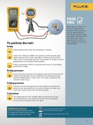
789 PROCESSMETER


Pressure
Gauge

100%
MIN MAX
RANGE
HOLD
SpanCheck
%STEP
COARSE
FINE
TECH
0%
REL
Hz
mV mA
TIPS
VA
V mA Hand
OFF
OUTPUT
Pump
mA
250 mA
When you use a Fluke 754 HART LOOP POWER
OUTPUT 0-24mA
SOURCE SIMUL ATE
A mA COM V
or 3130 to automate the Pressure Input
pressure switch calibration,

vary the applied pressure
slowly, back and forth across

the setpoint and reset points.
The display will make it

apparent that the set/reset
has changed and the actuals To perform the test:

will be logged.

Setup

Safely disconnect the device from the process it controls.
STEP
1


STEP Connect the calibrator or DMM to the common and NO (normally open)
2
output terminals of the switch. The DMM or calibrator will measure an
“open circuit”. if measuring continuity. If measuring V ac be sure the tool is

properly rated for the voltage being measured.

STEP Connect the pressure switch to a pressure source such as a hand pump
3
connected to a gauge.


Rising pressure


STEP Increase the source pressure to the setpoint of the switch until the switch
4
changes state from open to close. Manually record the pressure value

when the DMM indicates a “short circuit” or if using a calibrator it will
record the value for you.


Falling pressure


STEP Continue to increase the pressure until the maximum rated pressure.
5
Slowly reduce the pressure until the switch changes state again, and

resets from closed to open, then record the pressure.

Calculation


STEP The setpoint pressure was recorded when the pressure was rising.
6
The deadband value is the difference between the rising setpoint

pressure and the falling pressure reset point.


Additional resources
See the pressure switch test video at:
For more in depth information about www.luke.com/pressureswitch

this application check out these videos
and application notes from Fluke.
Calibrating pressure switches with a DPC


9