Page 20 - 810 Trianing Book Extract
P. 20
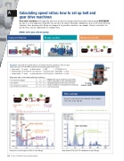
A Calculating speed ratios: how to set up belt and

gear drive machines


Gear-drive machines will typically have four (or more) bearings and two (or more) shafts going DIFFERENT
speeds. It is very important to identify the speed of all shafts. If possible, inding the gear teeth count will help
eliminate false bearing calls. Below are images of a gear-drive machine, an example of how to calculate the

speed ratios, and an explanation of example data.

Motor with gear-driven pump


Component diagram
Example machine
Machine icon in 810


Gearbox
Flexible coupling


Gearbox


Example: calculate the speed ratios on a double reduction gearbox, with an input
speed (motor) of 1775 RPM, and with the following gear teeth count:
21
Motor
• Input shaft: 21 teeth ➔ Motor shaft = 1XM = 1775 RPM = 1X
• Intermediate: 67:31 teeth ➔ 1st reduction = (21/67)x1775 = 556 RPM = 0.31X
Output shaft: 71 teeth 2nd reduction = (31/71)x 556 = 243 RPM = 0.14X
• ➔
67/31
More gear sets = more data collection locations:
Note: Rare faults related to gear teeth
# of speed changes
1
2
3
will be reported as non-standard faults.
(Standard faults are the four common 71
# of shafts
2
3
4
To pump
faults: imbalance, misalignment, bearings, (output shaft)
and looseness)
# of collection locations
2
3
4


Hints and tips


If gear teeth count is not known, then simply
enter the shaft speeds.


Motor shaft = Intermediate shaft = Pump shaft
1XM
0.31XM
= 0.135XM

Gear Mesh = 21X (1XM X Gear teeth)


Motor harmonics


1X sidebands
Intermediate shaft
harmonics
around Gear Mesh


Output shaft
harmonics


Harmonics of motor/gear shafts in Low Range
Gear Mesh (21X) with 1X sidebands in High Range


138 Section 2: Vibration tester training manual